In the present day, electricity is treated as one of the basic requirements of human beings. But, the cost of making electricity is risky for the environment. According to the energy information records, approximate 50% of all electricity plants are contaminating coal plants. Various changes in the environment have happened over the last thirty years, which are injurious to the forthcoming of this planet. To overcome this, here is a solution to diminish greenhouse gas emissions into the soil’s atmosphere through an alternative power generation. One sustainable technology leading this charge is WPT (wireless power transmission) or IPT (inductive power transfer).
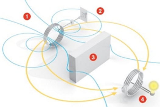
WPT technology is old technology and it was demonstrated by “Nikola Telsa” in the year 1980. Wireless power transmission mainly uses three main systems such as microwaves, solar cells, and resonance. Microwaves are used in an electrical device to transmit electromagnetic radiation from a source to a receiver. Accurately the name WPT states that the electrical power can be transferred from a source to a device without using wires. Basically, it includes two coils they are a transmitter coil & a receiver coil. Where the transmitter coil is powered by AC current to create a magnetic field, which in turn induces a voltage in the receiver coil. The basics of wireless power transmission include the inductive energy that can be transmitted from a transmitter coil to a receiver coil through an oscillating magnetic field. The DC current supplied by a power source is changed into high-frequency AC current by particularly designed electronics built into the transmitter.
In the TX (transmitter) section, the AC current increases a copper wire, which creates a magnetic field. Once an RX (Receiver) coil is located near to the magnetic field, then the magnetic field can induce an AC current in the receiving coil. Electrons in the receiving device convert the AC current back into DC current, which becomes working power.
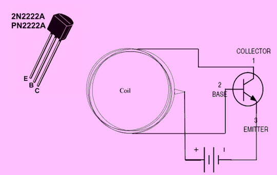
The simple wireless power transmission circuit is shown below. The required components of this circuit mainly include 20-30 magnet wire (gauge copper wire), A battery-1, transistor (2N2222) and LED. The construction of this circuit comprises a transmitter and a receiver.
Take a PVC pipe and whirl a wire on it seven times after whirling a wire about three inches make a loop for center terminal and continue the process. Now take transistor 2N2222 and connect its base terminal to one end of the copper coil, the collector terminal to the other end of the copper coil and now connect the emitter terminal to the negative (–ve) terminal of an AA battery. The center terminal of the copper coil will be connected with the positive (+ve) terminal of an AA battery. When then the receiver coil is placed 1 inch above the transmitter coil, then the LED will blink.
The wireless power transmission can be defined as the energy that can be transmitted from the transmitter to a receiver through an oscillating magnetic field. To accomplish this, power source (DC current) is changed into high-frequency AC (Alternating Current) by particularly designed electronics erected into the transmitter. The AC boosts a copper wire coil in the transmitter, which produces a magnetic field. When the receiver coil is placed in proximity of the magnetic field, the magnetic field can make an AC (alternating current) in the receiving coil. Electronics in the receiving coil then alter the AC back into DC which becomes operating power.
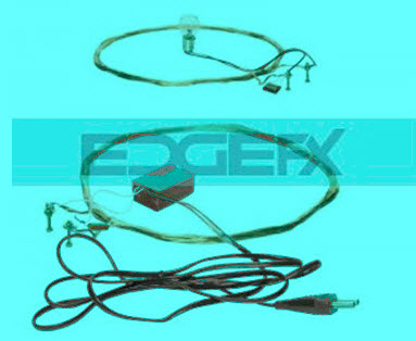
The main intention of this project is to design a WPT system in 3D space (transfer power within a small range) and the block diagram of this project is shown below. The block diagram of the wireless power transfer mainly builds with HF transformer, capacitors, diode, rectifier, inductor coil filled with air and lamp. The person is mandatory to be worked every year to change the battery. This project is designed to charge a rechargeable battery wirelessly. Since charging of the battery is not possible to be demonstrated, we are providing a DC fan that runs through wireless power. Thus the power transfer can be done with the transmitter (primary) to the receiver (secondary) that is separated by a considerable distance (say 3cm). Therefore the power transfer could be seen as the TX transmits and the RX receives the power to run a load.